The Interaction of Mean or Weld Residual Stress with the Neuber Plasticity
Correction and the Effects on Fatigue Life Prediction
A.Conle
Nov. 2 2014, Updates: Dec 6 2014
Copyright (C) 2014 A.Conle and Univ. of Waterloo
Permission is granted to copy, distribute and/or modify this document
under the terms of the GNU Free Documentation License, Version 1.3
or any later version published by the Free Software Foundation;
with no Invariant Sections, no Front-Cover Texts, and no Back-Cover Texts.
A copy of the license is available here:
"GNU Free Documentation License".
( "http://www.gnu.org/licenses/fdl.html" )
Introduction:
The presence of mean stress in fatigue tests of metals has been known
to affect the subsequent fatigue life. See Refs.: [1-5]. Generally
a tensile mean stress will reduce the initiation or propagation life when
compared to fully reversed (Zero mean) loading. Similarly compressive mean
stresses will prolong fatigue test life[5].
Fatigue design codes for welded structures [6-8] have commonly concluded
that a designer of a welded connection may ignore the mean stress in
fatigue loading cycles and simply use the stress range of a cycle to estimate
the fatigue damage. For small stress amplitudes the IIW [8] code appears to
allow the use of mean stress compensation in life estimates.
The present study examines the underlying reasons for the apparent unimportance
of applied mean stress in terms of the effects of residual stress, local stress
and strains at stress-raisers and cyclic mean stress relaxation. The objective
is to determine when the nominal mean stress applied to welded components can
safely be ignored and under what conditions one would expect the applied mean
stresses to alter the expected fatigue life.
In most component or full scale fatigue testing the control variable is load
translated into a nominal stress near the weld line of interest. At the weld
itself there are commonly inherent stress raisers caused by weld fillet geometry,
porosity, spatter, slag inclusions etc. and these stress raisers often
magnify the nomial stresses into the plastic region of the material
at the weld fatigue "hot spot". The present article attempts to
examine the material cyclic behavior of the region at such a fatigue hot spot
in terms of the effects of initial residual stresses, the geometric stress
concentration factors and the fatigue test loading.
Assumptions and Starting Points:
- There will be residual stresses left behind by the welding process.
The magnitude of such stresses, in either tension or compression, is
limited approximately by material yield strength.
- There will also be geometrical stress-raisers caused by porosity,
slag inclusions, or other weld features. Their effect in terms of the
stress concentration factor Kt is listed:
- Surface Pit: Kt= 1.3 (Hiam [9])
- Internal Pore: Kt= 1.5 ( Gurney Table 9.2 [10])
- Slag Inclusions: Kf= 2 (Gurney Fig. 9.11 in [10])
- Machined Fillet: Kt=2.0-2.8 (Cordes[11], Perovic[12])
- Somewhere in the structure or component tensile weld residual stresses
will be at a stress raiser.
- Given sufficient plasticity in the local stress-strain hysteresis loops
at geometric stress-raiser, the residual stresses due either to welding
or prior loading can be "washed out" by cyclic mean stress relaxation [13-19].
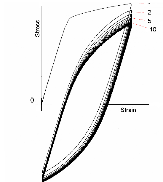
Figure 1 shows the phenomenon in the stress-strain response of an un-notched
specimen subjected to a strain limit controlled history. Strain
limit control is thought to be closer to conditions near the stress raiser
surrounded by an elastic field than load control test conditions.
- Weld material: It is not clear which material should be used for the
"base" fatigue properties ( i.e.: base metal, weld metal, or HAZ metal )
to compute local stresses and strains and crack initiation fatigue life
at the hot spot. [23-25]
- The present bridge and offshore structural design codes [6-8] suggest
that one can ignore the effects of mean stress when computing fatigue life
of welded structures.
- The Neuber plasticity correction[20-22] can be used to compute the local
stresses and strains at a stress raiser in a welded component subjected
to nominal elastic loads.
 (Click figure to enlarge)
Fig. 1: Cyclic mean stress relaxation during strain limit
control testing of an axial un-notched specimen.
(adapted from Langraf Ref.[18])
Relaxation- the Movie: animation.gif (Warning: 9.0Mb !)
Base Metal Fatigue and Cyclic Deformation:
Several papers have documented [15,23-24] the base metal, weld metal and HAZ
stress-strain-life fatigue curves for a number of steels. Leever [25] suggests
that many weld fatigue life predictions can be made by observing "hot-spot" strains
and then using a stress concentration factor of 2.0 applied to the unnotched axial
specimen fully reversed test results for ASTM A36 structural steel.
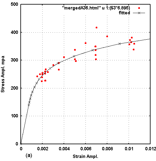
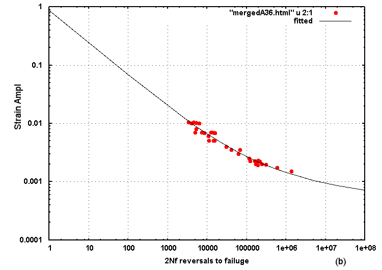
Fig. 2 : (a)Cyclic stress-strain data and fitted curve for merged files of A36 steel)
         (b)Strain-life fatigue data and fitted curve for merged files of A36 steel)
            Data files are available here.
In the following analysis sections the Neuber plasticity correction and the subsequent
local stress-strain and fatigue life estimations utilize the "Fitted" curve (black lines)
shown in Fig. 2 above. These fitted data points are available in the file:
Computing Local Stress-Strain using the Neuber Plasticity Correction
Determining the local stress and strain at the fatigue critical location is
one of the methods used in computing the fatigue life of a notched component.
A notched plate specimen,for example, has a geometric stress concentrator which
magnifies the nominal stress by a computed Kt to estimate the elastic stress at the
edge of the notch. The same method will be used in this study to compute the
local elastic stress at a weld flaw or geometric stress concentrator. These
"hot-spot" elastic stress estimates are often above the material yield and must
then be corrected for material plasticity.
The computational method used in this study is the
Neuber Plasticity Correction.
Briefly; the method translates the elastic energy of estimated stress times strain
into the same value of energy using the cyclic stress-strain curve. When applied
sequentially on a half-cycle by half-cycle basis one can estimate the local stress-strain
history at a given stress raiser. More details are available at the above link.
Similarly in elastic finite element analysis (FEA) the predicted elastic stress at
a geometric stress raiser can easily be above the material's yield stress. No
further stress concentration factor generally needs to be applied i.e.: the computed
elastic stresses serve as the "nominal stresses" of a component with Kt=1. In order
to predict the local stress and local strain behavior one must still apply a correction
for material plasticity to the elastic nominal FEA stresses.
Application of Neuber Plasticity Correction: Kt=1
The present study will use the cyclic stress-strain curve for the A36 steel described
in a section above to predict the local stress-strain of a component by applying
an on-line
calculator to compute the local stresses and strains and the consequent
predicted fatigue life.
In this section we will examine the local results for a series of simulations that
all apply the same cyclic amplitudes of a nominal "elastic" input of +/-172.5 mpa
(+/-25 ksi) but vary the mean nominal level in each simulation.
The first simulation applies a nominal cyclic stress of Smax=172.5 mpa (25 ksi) and
Smin=-172.5 mpa (-25 ksi) with a nominal mean stress of So=0. The resulting local
stress-strain path and consequent fatigue life result, is shown in figure 3.
The path starts at the origin, rises to the maximum, reverses direction and proceeds to
the minimum, reverses again and then closes the hysteresis at the tensile maximum.
Of these the first half-cycle follows the shape of the cyclic stress-strain curve.
The half-cycles that form the hysteresis loop follow a shape that is a double of the
cyclic curve (Masing [26]).
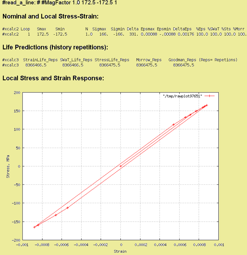
Fig. 3: Local stress-strain and fatigue result of a +/-172.4 mpa nominal elastic
input. (Kt=1)
In a similar manner, for a nominal stress ratio R=Smin/Smax=0.1 (a test commonly
performed to avoid buckling of samples), for Smax=383.3 (55.5ksi) and Smin=38.3 mpa (5.5ksi)
the resulting local stress and strain values are shown in figure 4. The nominal mean
stress for this case is So=210.8 mpa (30.6ksi). In a test situation that imposed these
stresses on a specimen, the stress would first be raised to the nominal level of So,
indicated by the blue spot on the figure's elastic line. The Neuber plasticity corrected
location for the nominal So is shown by the orange spot on the cyclic curve. Such an
initial loading, or imposed mean stress, is then followed by the cyclic fluctuations that
would range from +383.3mpa to 38.3mpa (nominal), and are shown by the hysteresis loop
in local stress and strain after correction for plasticity. The local loop has a peak
stress of 279 mpa and a minimum stress at -61 mpa which gives it a tensile mean stress
of 105 mpa. Although not used here a similar result would have been achieved if one
used the virgin monotonic tensile curve to do the initial excursion. The 0.2% offset yield
for A36 is about 265 mpa.
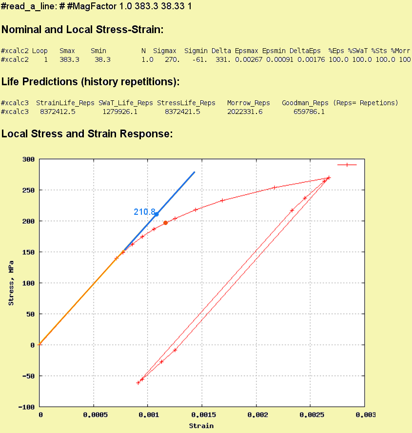
Fig. 4: Local stress-strain and fatigue result of a Smax=383.3, Smin=38.3 mpa
nominal elastic input. (R=0.1, Kt=1)
When one increases the nominal mean stress to So = 345 mpa and maintains the same cyclic
amplitudes around this mean the local stress-stain result is shown in Fig. 5. The local
stress-strain for a nominal So=345 mpa is shown as a red dot on the cyclic curve. The
resulting local mean stress of the hysteresis loop increases to 140 mpa, which is a 33%
increase compared to the nominal mean stress increase of 64% when compared to the R=0.1
result above.
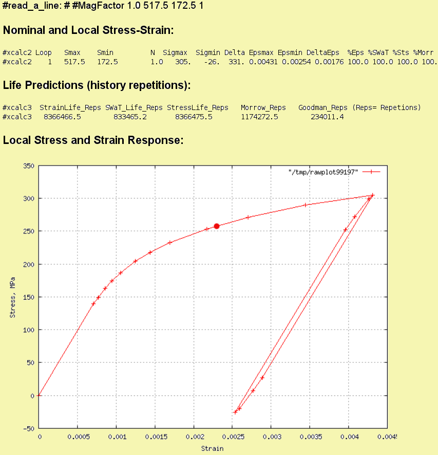
Fig. 5: Local stress-strain and fatigue result of a Smax=379.5, Smin=34.5 mpa
nominal elastic input. (R=0.333, Kt=1)
Increasing the nominal mean stress again to So = 690 mpa and maintaining the same cyclic
amplitudes around this mean level results in a local stress-strain path shown in Fig. 6.
The nominal mean stress applied initially results in a local stress of 339 mpa (red dot)
and the cyclic hysteresis loop's mean stress is computed to be 200mpa. Hence when
compared to the R=0.1 computation the nominal mean stress has increased by 230% while the
local mean stress only increased by 90%
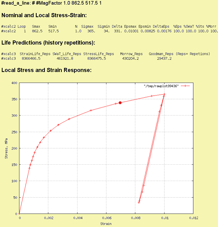
Fig. 6: Local stress-strain and fatigue result of a Smax=379.5, Smin=34.5 mpa
nominal elastic input. (R=0.6, Kt=1)
It is generally accepted in the literature that for unnotched specimens loaded axially
that one must use a correction parameter to compensate for the effects of mean stress
when using fully reversed strain controlled test data. For local hysteresis loops with
tensile mean stresses the Smith/Watson/Topper (SWT) parameter[4] is believed to give good
results[5], and for compressive local mean stresses the Morrow[5] mean stress correction
appears to give the best results.
When one does not apply a mean stress correction in the four cases shown in the figures
above, the computed life, based simply on strain amplitudes, is Nf=8.37 million cycles.
The Smith/Watson/Topper correction for the means show are also indicated in the figures
and summarized as follows
                         Table 1

                   Sigma   Sigma      SWT
            R       max     min        Nf
           ----    -----   -----    -----------

           -1      166    -166      8,366,000

           0.1     270     -61      1,280,000

           0.333   305     -26        833,000

           0.6     365      34        462,000

     SWT parameter is based on     sqrt( Sigma_max * StrainAmpl. )
         where in present cases local StrainAmpl= 0.00088
What has not been addressed in these computations is the effect of cyclic mean
stress relaxation. When the local stress-strain loop has sufficient plasticity
the local mean stress will decrease towards the zero stress axis with repeated
cycling [13-19]. An on-line version of
Ref.[14] is available here.
In
figure 3 from this reference
one can deduce that the local loops shown in the
above figures, that have only a strain range of 0.00176 (0.176%), will not substantially
relax their mean stresses with cycling. The predictions of Table 1 therefore do not
need further adjustments.
Welded Specimens with a Kt=2
As described in the earlier sections of this report the geometric stress raiser effects
of welded metal tend to cause a stress concentration of approximately Kt=2.0.
The following examines the effects on the local stress-strain loops of introducing
such a magnification factor on the elastic analysis. i.e. a Kt=2.0 is the same as
multiplying the elastic nominal stresses of the previous section by a factor of 2.
Note that the original cyclic stresses at R=-1 Kt=1.0 create a fatigue prediction of
Nf=8.3 million cycles, which could be considered the fatigue limit for this material.
The factor of Kt=2.0 will be applied to both the initial mean nominal stress, So, and the
following cyclic nominal stress amplitudes or limits Smax and Smin. As in the previous
figures the nominal So when corrected for plasticity is indicated by a red dot in the local
stress-strain co-ordinates.
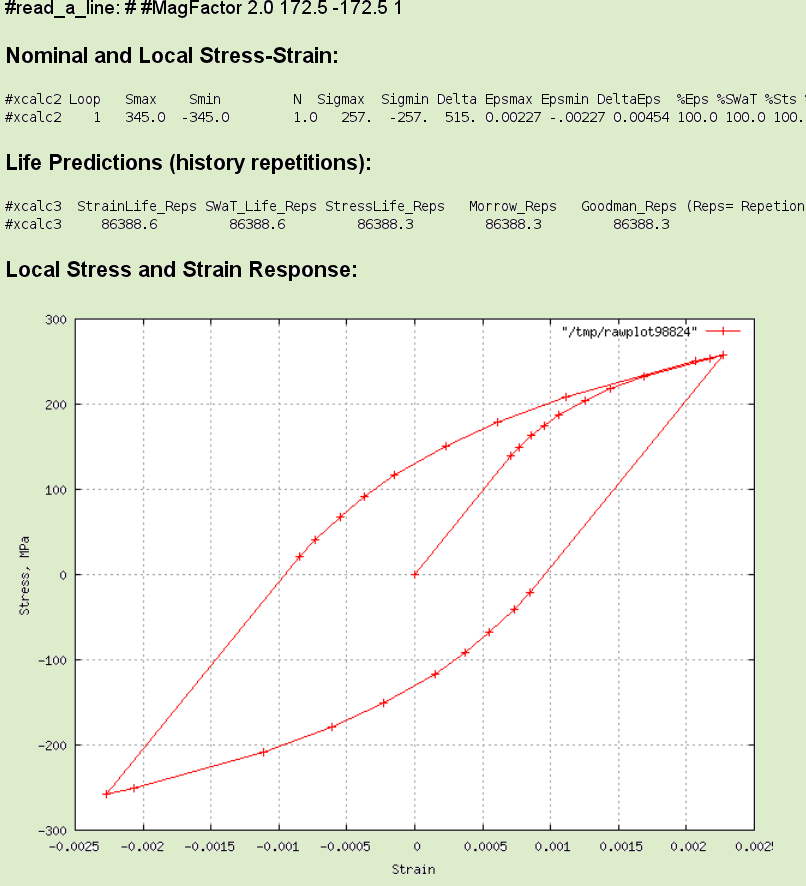
Fig. 7: Local stress-strain and fatigue result of a Smax=172.5, Smin=-172.5 mpa
nominal elastic input. (R=-1, Kt=2)
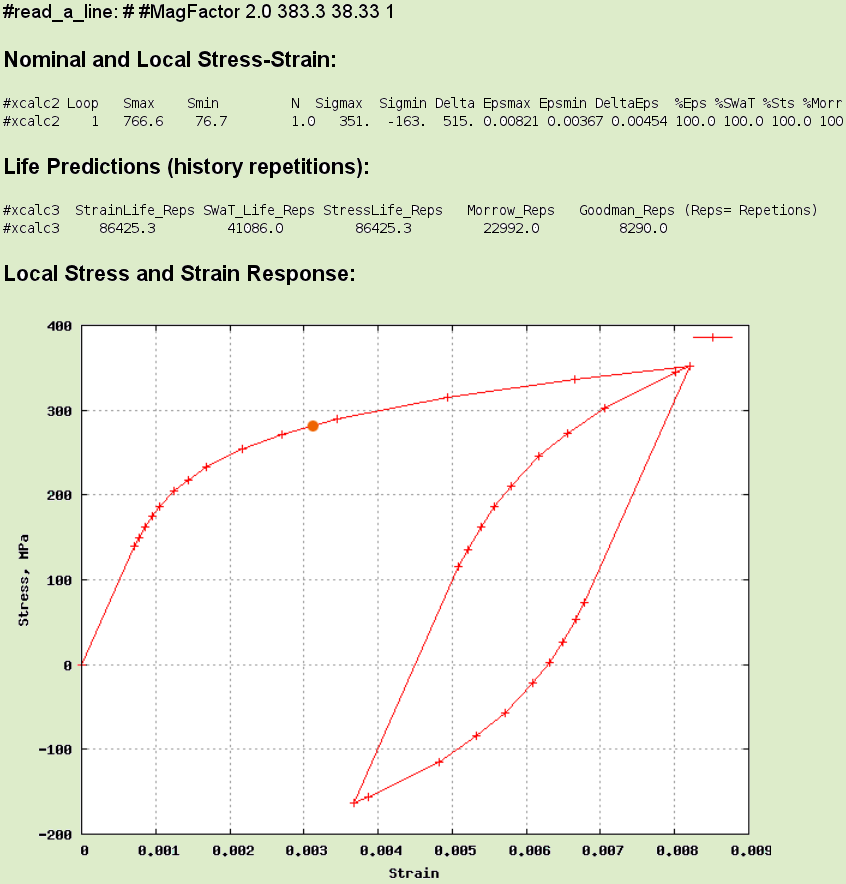
Fig. 8: Local stress-strain and fatigue result of a Smax=383.1, Smin=38.3 mpa
nominal elastic input. (R=0.1, Kt=2)

Fig. 9: Local stress-strain and fatigue result of a Smax=517.5, Smin=172.5 mpa
nominal elastic input. (R=0.333, Kt=2)
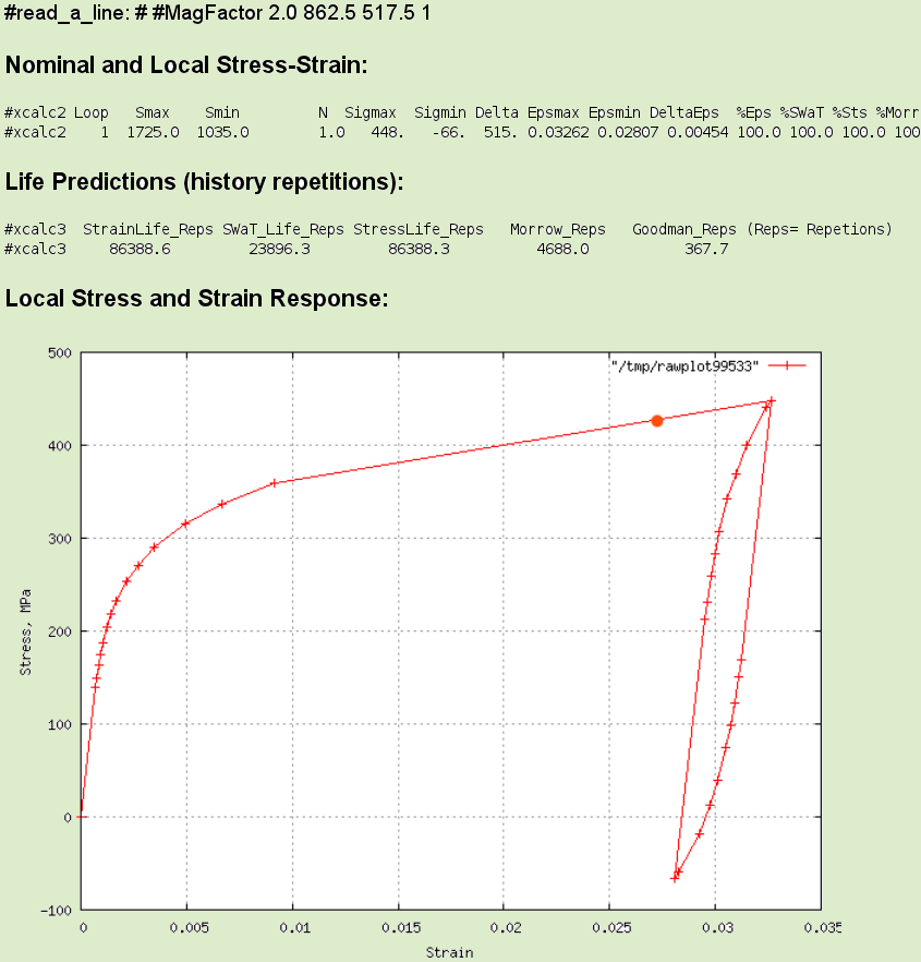
Fig. 10: Local stress-strain and fatigue result of a Smax=862.5, Smin=517.5 mpa
nominal elastic input. (R=0.6, Kt=2)
Due to the magnification of the stresses by the assumed Kt=2 the local stress caused by
the nominal mean So, varies between 281 and 419 mpa. The strain range of the local loop
however has now increased to 0.00454 (0.45%) which based on the
cyclic stress relaxation
data predicts that the local mean stress would relax to zero within about 100 fatigue cycles.
This implies that for components with a stress raiser of Kt=2, within the first 100 cycles
all mean stress, or residual stress, due either to the imposed load history or the welding
induced residuals would disappear.
Large Cycle + Small Cycle Effect
Fatigue simulations for vehicles or structures often assume that the characteristic
design load history will repeat. A vehicle for example may be driven a few hundred
times over the same proving grounds, or a structure may be assumed to be subjected
to several similar severe storms. The largest loading event in such a repeated sequence
will created an overall large local stress-strain hysteresis loop. All smaller load cycles,
due to material memory, will be constrained to be inside this largest loop. The smaller
loops must be attached to the largest loop in some way by the stress-strain path.
If one places a simplified two event history into the fatigue calculator:
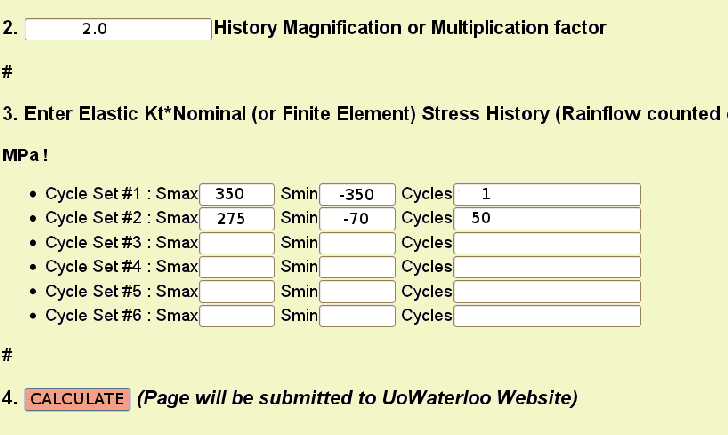
then the returned simulation of local stress-strain and fatigue damage will show
a large overall hysteresis loop, in this case one with zero mean stress, and a
smaller loop that is attached to the top half-cycle of the larger loop:
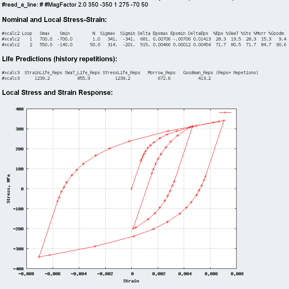
Fig. 11: Local stress-strain and fatigue result of a two cycle set
nominal elastic input history.
Even though the smaller loop has enough plasticity to wash out any mean stress in
about 100 cycles, after only 50 repetitions of the smaller loop, the larger
loop will again occur and re-instate the smaller loop's mean stress. Thus effectively
one should ignore mean stress effects for damage computation for the larger loop,
but compensate for the tensile mean stress of the smaller loop's fatigue damage
summation. Note that in the percent damage line (under "Nominal and Local
Stress-Strain") that the damage of the 50 smaller loops are doing 70% to 80%
of the total damage: %Eps=71.7 ___ %SWT=80.5.
At this time most of the software, either commercial or public, does not differentiate
for mean stress relaxation in such cases, and simply assumes that the mean stress
is fully effective for the fatigue life calculation. It should also be pointed
out here that the Rainflow or Reservoir Cycle counting methods in common usage
do not really keep track of whether the smaller loop should be attached to
the top half-cycle or the bottom half-cycle of the larger loop or to some other
intermediate sized loop in the middle of the big one. That information
is lost in the counting process and an assumption must be made.
Hypothesis
The above calculations suggest that it is not the presence of the residual stresses in weldments
that negates the effects of nominal mean stresses in a fatigue history, but the magnification
of the local stresses and strains by the geometric stress raisers created by the welding that
causes sufficient plasticity in the local stress-strain hysteresis loops to cyclically
relax their mean stresses. A fully relaxed zero mean stress local hysteresis loop requires
no mean stress computational adjustments, and a simple use of local stress range or local
strain range will yield the appropriate fatigue prediction.
It is expected that for small cyclic nominal stresses that, when amplified by the Kt=2, show
little plasticity in the local stress-strain hysteresis loops, that compensating for mean
stress will again be important for accurate life prediction.
References:
- H. Gerber, "Bestimmung der zulaessigen Spannungen in Eisen-Constructionen,"
(Calculation of the allowable stresses in Iron construction), Zeitschrift des
Bayerischen Architekten und Ingenieur-Vereins, V6, N6, 1874, pp.101-110.
- J. Morrow, "Fatigue Properties of Metals," in SAE Fatigue Design Handbook,
1968, pp.21-30.
- T.H. Topper and B.I.Sandor, "Effects of Mean Stress and Prestrain on Fatigue-Damage
Summation," ASTM STP 462, 1970, pp.93-104.
- K.N. Smith, P.Watson, and T.H.Topper, "A Stress-Strain Function for the Fatigue of
Metals," J. of Materials, V5, No4, Dec. 1970, pp.767-778.
- "SAE Fatigue Design Handbook," AE-10 2nd Edition, Soc. Autom. Engrs., 1988.
- B. Kuehn, et al, "Assessment of Existing Steel Structures: Recommendations for Estimation of
Remaining Fatigue Life," JRC Euro. Commission, First Edition, Feb. 2008 EUR 23252 EN-2008
- Det Norske Veritas,"DNV-RP-C203 Fatigue Design of Offshore Structures," Apr. 2010.
- Intern. Inst.Weld., "Recommendations for Fatigue Design of Welded Joints and Components,"
IIW document IIW-1823-07 Dec. 2008
- J. Hiam, R.Pietrowski, "The Influence of Forming and Corrosion on the
Fatigue Behaviour of Automotive Steels," SAE Technical Paper 780040, 1978.
- T.R. Gurney, "Fatigue of Welded Structures," Cambridge at the University Press, 1968.
- T. Cordes, "F.D.+E Total Life Project 1,"
Overview
at https://fde.uwaterloo.ca/Fde/CaseStudies/casestudies.html
- Z.D. Perovic, "The Weld Profile Effect on Stress Concentration Factors in Weldments,"
15th Intern. Res./Expert Conf. "Trends in the Development of Machinery and Associated
Technology" Prague, Czech Republic, 12-18 Sep. 2011.
http://tmt.unze.ba/zbornik/TMT2011/236-TMT11-025.pdf
- J.Morrow, G.M.Sinclair, "Cycle-Dependent Stress Relaxation," ASTM Symp. on Basic
Mechanisms of Fatigue, ASTM STP No. 237, 1959.
- A. Conle,
"Data on Cyclic Mean Stress Relaxation in Mild Steel,"
3A Civil Engr. Work Term Report, April 1970
- Y. Higashida, J.D.Burk, and F.V.Lawrence jr, "Strain-Controlled Fatigue Behavior
of ASTM A36 and A514 Grade F Steels and 5083-O Aluminum Weld Materials,
Welding Res. Supplement Nov.1978, pp.334s-344s.
- R.W. Landgraf and R.C.Francis, "Material and Processing Effects on Fatigue
Performance of Leaf Springs," SAE Paper 790407, 1979.
- R.W. Landgraf and R.A.Chernenkoff, "Residual Stress Effects on Fatigue of
Surface Processed Steels," ASTM STP 1004, 1988, pp.1-12.
- R.W. Landgraf, "The Resistance of Metals to Cyclic Deformation," ASTM STP 467,
1970 pp.3-36.
- R.A. Chernenkoff, "The Effect of Cyclic Loading on the Residual Stresses of a Shot
Peened Powder-Forged Copper Steel," MSc. Thesis, Wayne State Univ. 1993.
- H.Neuber, "Theory of Stress Concentratioin for Shear Strained Prismatical Bodies
with Arbitrary Non Linear Stress Strain Law," J.Applied Mech., Dec. 1961, p.544.
- T.H.Topper, R.M.Wetzel, J.Morrow, "Neuber's Rule Applied to Fatigue of Notched
Specimens," ASTM J. of Materials, V4 N1 March 1969, p.200.
- F.A. Conle, "Plasticity Corrections for Elastic Analysis Results: Neuber Method,"
https://fde.uwaterloo.ca/Fde/Notches.new/neuber.html
Nov.8 2010, Updates: Jan2012, Sep2012, Jan2013
- D.B. Robins, "Fatigue Strength of Welded Structural Elements," MSc.(Civil) Thesis,
U.Waterloo, Aug.1969.
Weld Metal 1522H
- A.M.van der Zanden, D.B.Robins, T.H.Topper, "Fatigue Life Prediction for Weldments
with Internal Cavities," ASTM STP 515, 1972, pp.268-284.
- R.C. Leever, "Application of Life Prediction Methods to As-Welded Steel Structures,"
ASME Int. Conf. on Advances in Life Prediction Methods, The Matls. Conf, Albany, NY,
Apr. 18-20, 1983. Lib. of Congress 83-70330.
- G. Masing, "Eigenspannungen und Verfestigung beim Messing," in Proceedings 2nd Intern.
Congress of Applied Mechanics, Zurich, 1926.
 (Click figure to enlarge)
  (Click figure to enlarge)


