Copyright (C) 2020 F.A. Conle and Univ. of Waterloo
Permission is granted to copy, distribute and/or modify this document
under the terms of the GNU Free Documentation License, Version 1.3
or any later version published by the Free Software Foundation;
with no Invariant Sections, no Front-Cover Texts, and no Back-Cover Texts.
A copy of the license is available here: "GNU Free Documentation License".
( "http://www.gnu.org/licenses/fdl.html" )
Introduction:
One of the objectives of durability analysis is to predict the magnitudes
of the local cyclic stresses and strains experienced at the hot-spot of
many components subjected to fatigue loading. Most estimates of component stress however,
have been calculated elasticly, by means of either traditional manual calculations
or elastic FEA methods. It is then necessary to translate the elastic
calculated stress at the critical locations into estimates of elastic-plastic
stress and strain behavior. Of the several methods of accomplishing this
translation, the one most popularly adopted by most software methods is the
Neuber [1-3] plasticity correction.
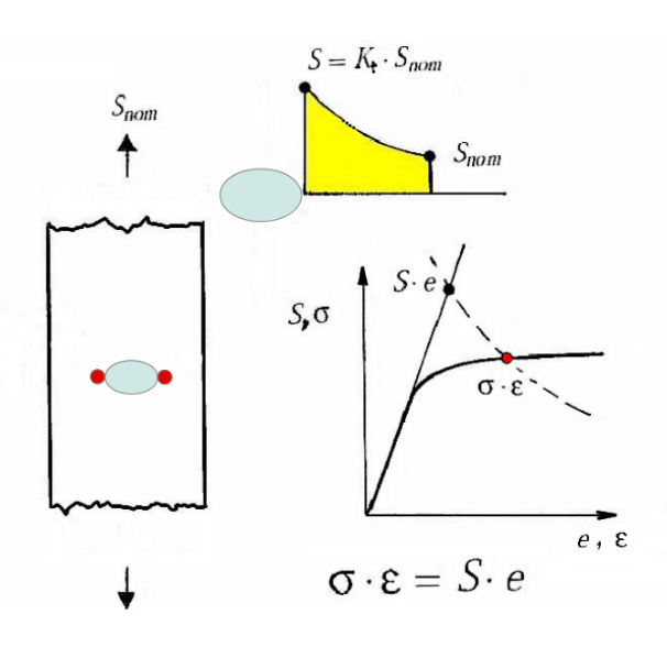
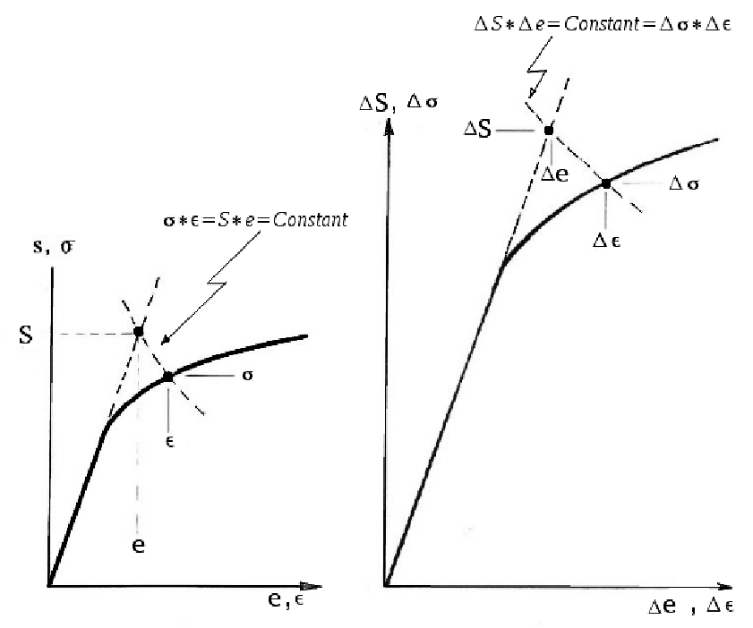
Fig. 1 : Correcting an Elastic Stress Calculation for Material Plasticity
As depicted in Fig._1, the Neuber correction can be set into three
steps:
Using elastic calculation methods compute the stress and strain
at the fatigue hot-spot.
Compute the energy or product of elastic stress multiplied by
elastic strain.
Using the stabilized cyclic stress-strain curve of the material
at the hot-spot find the cyclic stress and cyclic strain that
give the same energy product as in Step 2.
One can find examples of the stabilized cyclic stress-strain curve
in fatigue databases such as
here.
When you find the material of interest
e.g.:
Click on the "Fitted" link and using either "View Page Source" in your
browser or "cut and paste",
extract the stress and strain columns
from the data section.
Cyclic Stress-Strain Behaviour:
Fig. 2a shows the stress-strain behavior of a un-notched, axial sample starting from
the initial stress-strain origin with subsequent straining through a series of
simple fluctuating strain (or stress) cycles. It is apparent that the Fig. 2a : Movement of the stress strain locus during straining
of cyclically stabilized aluminum
initial loading path from the origin is different in size than the loading path
of the subsequent hysteresis loops. A commonly used approximation is that the
cyclic path is a factor of two larger than the initial path. Generally this is
referred to as "Masing" type behavior[4,5]. Similar behavior is exhibited in
multiaxial cyclic conditions[6,7], but for many fatigue problems a one-dimensional
approach suffices. An example of a strain sequence for HSLA 350 steel:
Fig. 2b : ( If image above is not "moving" hit "Shift + reload" on browser. )
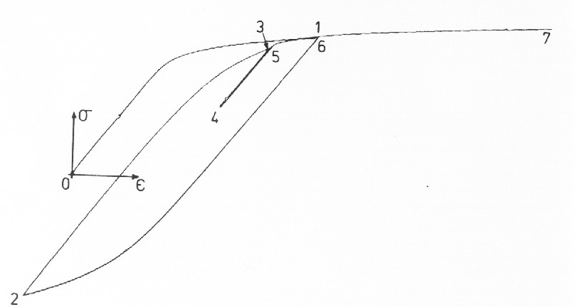
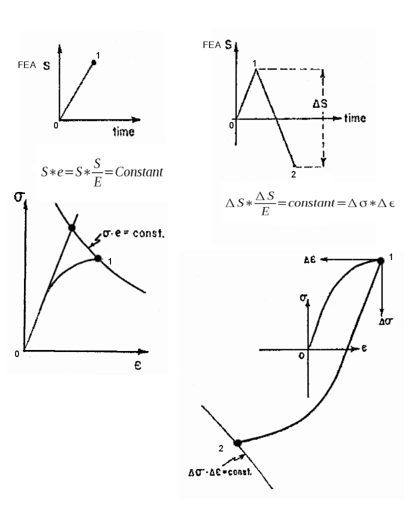
A schematic of the solution method of both the initial and cyclic Neuber based
plasticity correction is shown in Fig._3 and their application to two half cycles
are shown in Fig._4.
There are two similar curves shown in figure_3. The one on the left side is the
stabilized cyclic stress-strain curve generally derived from uniaxial fatigue test
samples, while on the right is the same curve with co-ordinates multiplied by a factor
of two. Both curves use the equivalent elastic energy product to solve for the
stress-strain magnitudes of each half-cycle of the loading history.
Fig. 4: Application of Initial and Cyclic Neuber Solutions.
More details of how these features are modelled for fatigue purposes can be
found in reference_[8].
Calculation Software
In the
fatigue database
of this web site there are typically three entries for each
data set. An example:
The first item, on the left is a text display and of the "raw" fatigue
test data. Data can be added to these files, either on-line or locally, and plots
created by clicking on the "Send" button.
The second item "_Fitted_" is a html file of a median line fit of the raw data.
It would be an input file for any software that performs a plasticity correction
and calculates the life based on the resulting local stress-strain hysteresis loops.
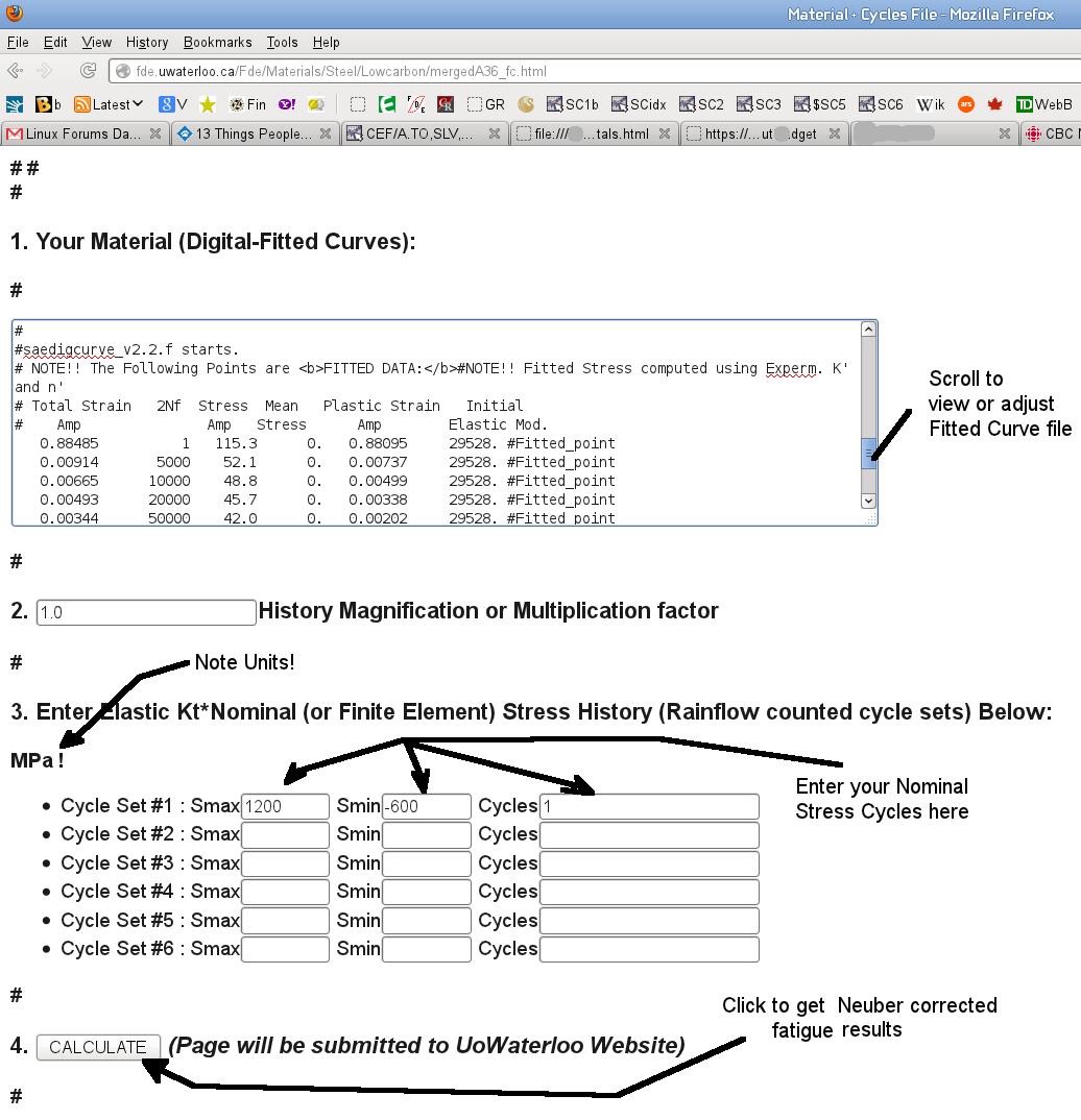
The third item, "_Calculator" is a html form which incorporates the "Fitted" file above,
and when submitted (click on Send), will calculate and display the local stress-strain
response to the nominal stress inputs as predicted by the Neuber plasticity correction.
Life is computed by using the local stress-strain loops maximum and minimum stresses and strains.
The software that performs these calculations is available in a link under the topic
Other Links below.
A screen shot image of how to use the calculators is
available here.
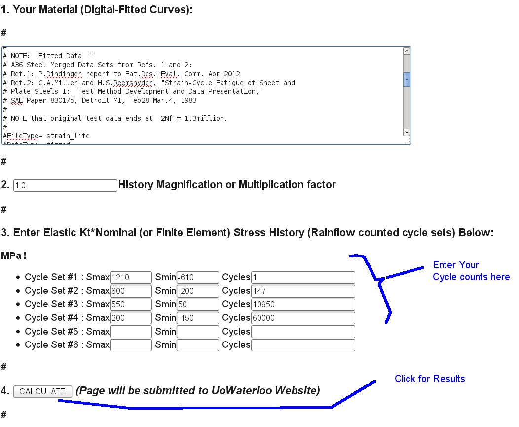
For an example set of screen shots of a typical usage with explanations:
If you found the gif video example at the top of this page interesting
you may like this one which adds a taper to the nominal stress history:
Short history with a taper
( 0.4Mb gif)
Neuber, H., "Theory of Stress Concentration for Shear Strained Prismatical
Bodies with Arbitrary Non Linear Stress Strain Law," J.Appl.Mech., Dec. 1961, pp. 544-550.
Topper, T.H., R.M.Wetzel, J.Morrow, "Neuber's Rule Applied to Fatigue of
Notched Specimens," ASTM, J.of Materials V4 N1, March 1969, pp.200-209.
Tipton, S., "A Review of the Development and Use of Neuber's Rule for Fatigue
Analysis," SAE Paper 910165, 1991.
Jenkin, C.F."Fatigue in Metals," The Engineer, Vol.134, No.3493, Dec. 1922, pp.612-614.
Masing, G., "Eigenspannungen und Verfestigung beim Messing," in Proc. of 2nd Int.
Congress of Appl. Mech., Zurich, 1926.
Mroz, Z., "On the Description of Anisotropic Work-Hardening," J.of Mech. Phys
of Solids, Vol.15 1967, pp.163-175.
Chu, C.-C., "A Three-Dimensional Model of Anisotropic Hardening in Metals
and Its Application to the Analysis of Sheet Metal Formability," J.of Mech. Phys.
of Solids, Vol.32, 1984, pp.197-212.
Conle, A., T.R.Oxland, T.H.Topper, "Computer-Based Prediction of Cyclic Deformation
and Fatigue Behavior," Low Cycle Fatigue ASTM STP 942, 1988, pp.1218-1236
Chu, C.-C, "Incremental Multiaxial Neuber Correction for Fatigue Analysis,"
SAE Technical Paper 950705, 1995