Servo-hydraulic Test System Control Software
FAConle
Created Sep30 2010, Updated: Dec.2011, Jan.2012
Copyright (C) 2011 F.A.Conle and Univ. of Waterloo
Permission is granted to copy, distribute and/or modify this document
under the terms of the GNU Free Documentation License, Version 1.3
or any later version published by the Free Software Foundation;
with no Invariant Sections, no Front-Cover Texts, and no Back-Cover Texts.
A copy of the license is available here:
"GNU Free Documentation License".
( "http://www.gnu.org/licenses/fdl.html" )
Introduction:
The application of small "mini" computers for control of servo-hydraulic
systems first became popular in the late 1960s. "Servo-hydraulic" systems
control the pressure on a hydraulic ram by means of an electrically positioned
servo-control valve. The ram pressure or displacement is electronically
monitored and used as a feedback control variable to form a closed loop process.
With the invention of A/D and D/A converters, it was possible to insert fast
response computer algorithms into the feedback control loop. Although the software
presented is designed for cyclic loading of fatigue specimens, the system could be
applied in many other data acquisition or test control roles.
The present web page outlines the construction of a typical PC based software
system to monitor and control a servo-hydraulic machine. The article's prime intent
is to outline how the computerization of older analog contollers may be achieved for
an inexpensive price.
System Description

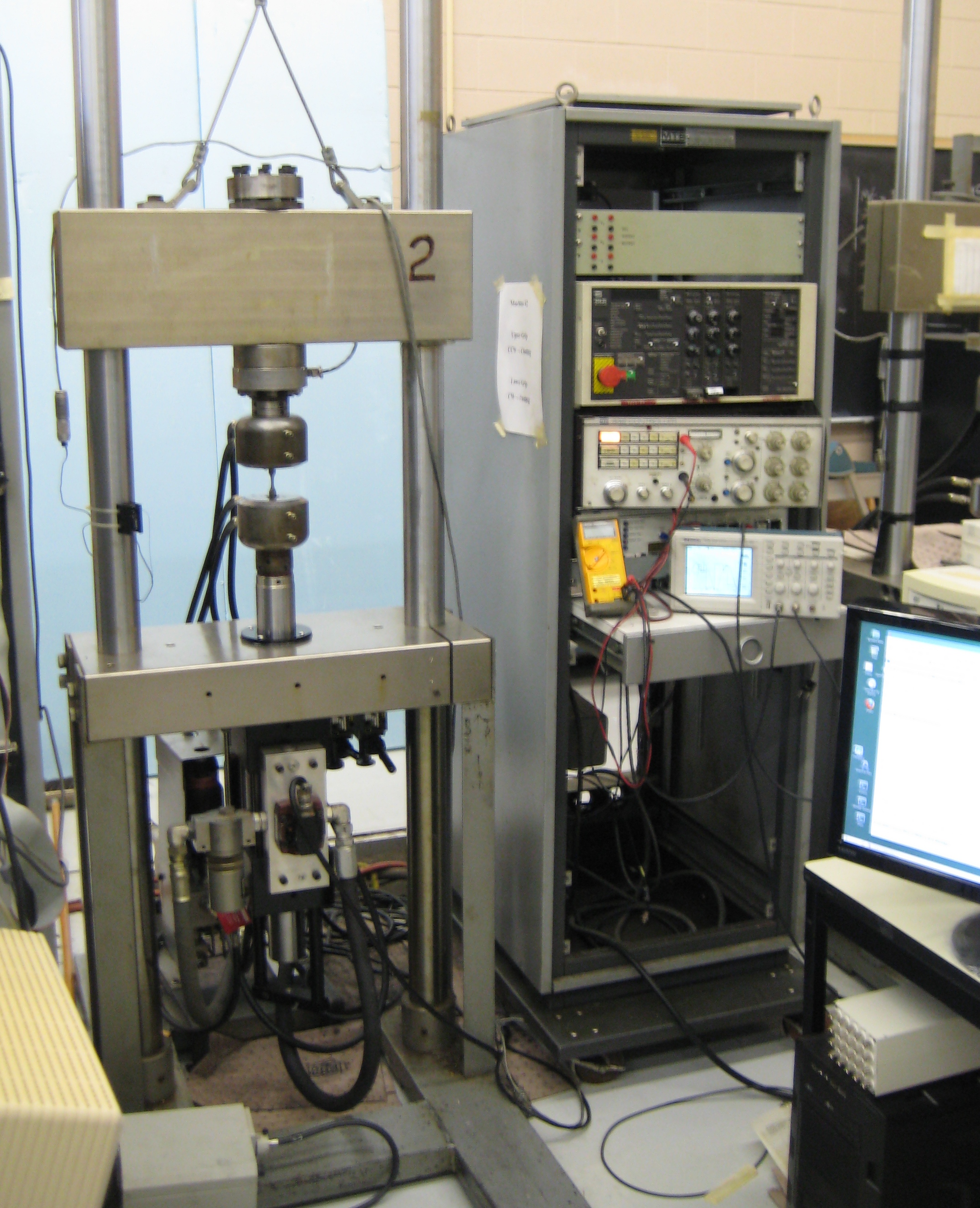
Fig. 1: Servo-Hydraulic frame and control electronics for testing
small sample metallic specimens.
(Click image to enlarge)
The computer hardware used in this case is a
Microstar Labs. DAP840 A/D + D/A board. The board runs a
version of MSDOS and talks to a user's PC(user side) via the PCI bus in a common desktop
computer case. The DAP 840 also requires a break-out box and cable for attachment of
the BNC cables to the analog voltage I/O or the experiment. Also needed is a
license for development DAP software which enables the compilation of user C++ written routines.
On the PC side of the computer one single system will require a Windows 2000 or better
operating system to compile the user written software for the DAP card. Any other systems
that you have do not require the complete DAP Development software as the programs can
be copied to the other test machine computers. The other systems simply require a DAP card
and an openSUSE Linux installation. On the development system the openSUSE Linux system is
installed alongside the MS Windows system such that either one can be booted at system
startup. The Linux o/s system is used to run the actual test and save/display the data output.
At the time of writing the overall expenditure for this example system was approximately
CDN$ 2000. to $3000 including the DAP card. Typical PCside options are 21in. or better monitor
for graphics, 2 core or more CPU, 500GB disk, DVD r/w, 4Gb memory, and an inexpensive graphics card.
An ethernet switch and router(to internet) are options that allow software updates and data files,
such as load histories or stress-strain responses, to be easily transfered between test machines
and allow user test observation and control from remote locations.
Fatigue Tests:
Fatigue testing using servo-hydraulic control for force or displacement
imposition on sturctures and smaller specimens has been used in engineering
for many years. The programs described in this article are primarily intended
for use in small specimen testing, but the software could also be applied for
testing of larger components. A servo-hydraulic control system generally uses
a feedback loop to control the ram force or displacement. Test control software
alters the command or target voltage in the feedback loop and monitors the
consequent changes of load cells, strain gages, stroke LVDTs etc to make a
algorithmic decision about the next command voltage to be imposed on the feedback loop.
In a typical constant amplitude load control test for example, the computer command
voltages are incremented in small (often millivolt) steps by means of the digital to
analog (D/A) converter on the DAP card, from initial 0.0_volts to perhaps +5.0_volts.
This voltage "ramp" may then be reversed and by decrementing the D/A converter, again
in small steps, to perhaps -5.0_volts. With repetition a triangular waveform is generated.
The output from the D/A serves as the command voltage to the load (or other variable) feedback
loop, thereby creating a triangular waveform loading history on the specimen or component.
Response voltages of the command feedback and other secondary variables are monitored through
the analog to digital (A/D) on the DAP840 board and used in computer control decisions or
transmitted to the user-side PC for display or to be saved on disk.
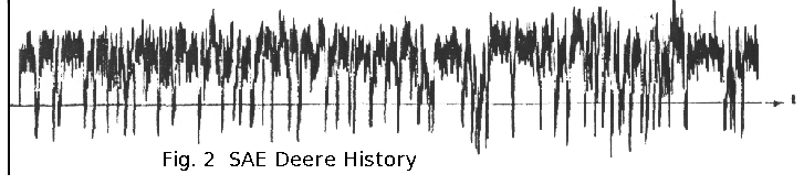
More complicated waveforms are created by simply changing the endpoints of the voltage ramps.
Displayed in figure_2 below is a popular variable amplitude testing history created by the
Fatigue Design and Evaluation Committee of SAE. The test frequency is determined by a number
of factors such as available hydraulic oil flow, servo-valve type, load train stiffness, heat
dissipation, etc. Typically in any feedback loop there is a delay between the time of D/A
command change and A/D observed response, and consequently special programming techniques
must be used to achieve higher cycle speeds. The programs provided here typically are used
in lower speed applications, where the phase-lag between command and response is less important.
Typical service load or proving ground
load history. (available
here.)
Software Variants:
- mlog2, mlog4, mlog6 : Simple logging of A/Ds to disk file.
- fgen10 : Triangular, Sinusoidal, and single Ramp function generator.
- mblk10 : Block program generator. Repeated Ramps: (high,low,reps.)
Since all the above test control programs are similar in their organization, only
the most complex of the group, mblk10 will be described in the outline below.
Test Control Program "mblk10" :
The mblk10 program consists of the following functional programs:
(Note that you may need to remove the ".txt" suffix from the filenames)
- mblk10s.cpp.txt : Control program that runs on the DAP840 board.
- mblk10.dap.txt : Short set-up module for DAP
- mterml_sh2.cpp.txt : PCside user program that transfers data to and from DAP
- Makefile.txt : use to build mterml_sh2
- mstun.cpp.txt : for run-time user interaction
- loopget.cpp.txt (vers 0.50) : to save 2 chan. of A/D at specific cycles and all max's and min's.
- saveLoopList.env.txt : environment file for loopget :
contains the list of cycle numbers for which loop data will be saved.
- massage1.txt : (script) Prepares all the hysteresis loop files
for plotting. You will need to make this script executable with the
command: chmod 744 massage1
- massage2.cpp.txt : (compile. Run by massage1)
creates a *.txt file for each hysteresis loop
- massage3.cpp.txt : (compile. Run by massage1)
creates one *.txt file for all the hystersis loops.
- massage.env.txt : environment file for massage*: calibrations etc.
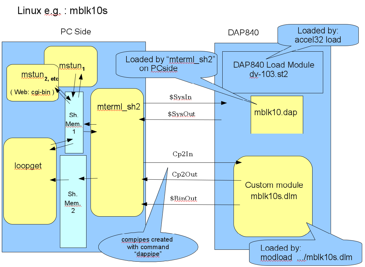
Figure 3 reflects the module arrangement in the two computers as set up for
the Univ. of Waterloo fatigue test lab.
Fig. 3: Map of typical custom operational modules in both PC and DAP.
(Click image to enlarge)
In the figure the flow of the text pipes is not strictly correct. The
DAP840 load module actually handles everything on the DAP and the pipes in
reality flow through it first, but conceptually for our understanding the
depiction above is close enough.
On the DAP840 side are two user created modules:
- mblk10.dap : is a short DAPL2000 program that is
just used to set up the A/D and D/A pipes that fee
values to and from the custom module
- mblk10s.dlm : is the cpp program created by the
user that reads the A/D values, implements the
servo hydraulic control logic, updates values to the
D/A, and communicates with the PC side program through
the BinOut and Comm pipes.
The PC side modules shown are also programmed in cpp:
- mterml_sh2 : a cpp program that initially acts as a
terminal emulator to load the mblk10.dap module
into the DAP, and then activates and initializes the user's
custom DAP module mblk10s.dlm. After the custom
module begins to control the test machine, mterml_sh2
is used to transfer the data flow from the custom to
disk or other display programs(via shared memory), and to
monitor the shared memory for command/requests from the user.
- Shared memory :
- Shared memory 1 (shm1) is created by mterml_sh2 and
shared by various user modules such as mstun.
Specific locations in this memory are used to display
running custom program outputs such as cycle number in
the load history, peak voltages, running voltage errors,
etc., and to transfer commands and requests from the user
activated mstun programs.
- Share memory 2 serves as a set of buffers for A/D data.
It is filled by mterml_sh2, with a flag set for each
buffer in shared memory 1, and is emptied by loopget.
- mstun : are small programs that attach to the shared
memory and transfer data from the user and the mterml_sh2
module. Commands such as stop, pause, restart, and are read from shm1
and bymterml_sh2 and then transfered to the DAP custom through
the Comm pipes. The modules also display test status variables such as
run state, cycle numbers, buffer status, etc. Multiple mstun
modules can be created and attached to allow the user to monitor and
control the test machine from the internet. Fatigue machines often run
overnight and its nice to be able to check tests from home.
- loopget : reads the A/D data transfered to shm2 by mterml_sh2
and selects specific cycle numbers, from a list provided by the user, for
storage in ascii files on the disk. These ascii files can then be directly
accessed by the user, or plotted using
gnuplot. Several standardized
plots for peak-valley-cycles or stress-strain hysteresis loops are available.
Source Code:
https://fde.uwaterloo.ca/Fde/Mstar/Source/index.html
Acknowledgements: This research was supported by NSERC of Canada,
the Univ. of Waterloo and the Univ. of Windsor. Many thanks to Larry Trammel
at Microstar for advice.