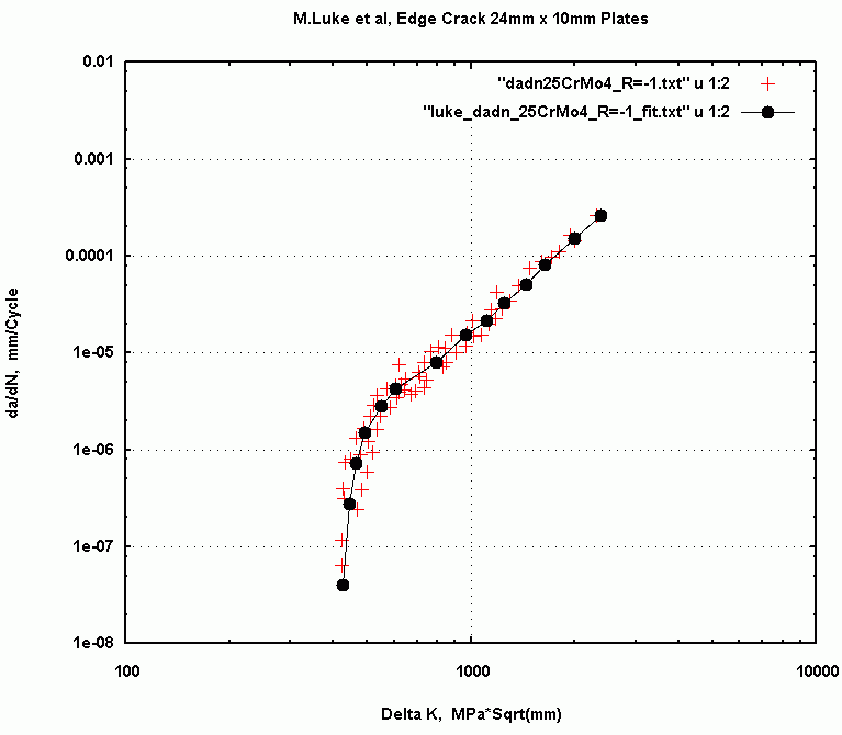
Fig. 1: Fitted da/dN points of 25CrMo4 Steel.
               25CrMo4  axle steel             Yield= 550 mpa

               34CrNiMo6  high strength steel       = 950 mpa
Plate specimens (width 24mm, thickness 10mm) used for generating baseline da/dN
Curves for da/dN baseline data were generated with tests using load ratios of
R=-1.0 and R=0.1 for both materials. R=-1.0 da/dN data from the reference
was fitted visually to the as shown if figure 1 and 2. (black points)
Fig. 1: Fitted da/dN points of 25CrMo4 Steel.
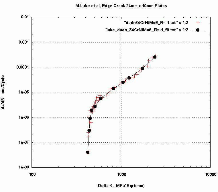
Fig. 2: Fitted da/dN points of 34CrNiMo6 Steel.
The original paper by Luke et al did not report any initiation tests.
The sub-blocks are divided into sub-block segments and the arrangement of
the segments is described in the text file
testLoads.txt
A program was used to convert the segment descriptors into a half cycle by
half cycle sequence. The program is available here:

Click to enlarge
A peak by peak history of membrane (Pm) and bending (Pb=0.0) are available
in the file
c100histPm.txt (1 Mb)
In the history the "100" value for the peak is proportional to the test reference stress
for sub-block 1 (the lowest stress sub-block). The arrangement of the sub-blocks and
their maxima stresses is a bit complicated and the reader is referred to the
paper by Luke et al for a full explanation.
34CrNiMo6 Steel:                                  Nf       af

             Delta S= 200 mpa  :  Fracture at    277000   7.7 mm
             Delta S= 200 mpa  :  Fracture at    298000   8.4 mm

             Delta S= 120 mpa  :  Fracture at   1380000   8.3 mm

25CrMo4 Steel:

              Delta S= 200 mpa :  Fracture at    156000   6.7 mm
              Delta S= 200 mpa :  Fracture at    159000   6.4 mm

              Delta S= 120 mpa :  Fracture at   1450000  10.0 mm


  (See Luke et al.  for experimental  crack length vs. cycles data plots )