The half tube thru tube "T" joint is shown in Figure 1. Tubing used for the
project was 0.312 inch wall and was welded with 5/16 inch weld.
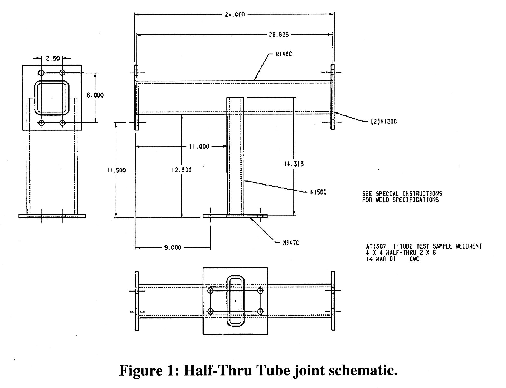
Fig.1: Click image to enlarge
Background: A "T" Tube welded joint has been employed in lab cycle testing.
The half tube thru tube "T" joint is shown in Figure 1. Tubing used for the
project was 0.312 inch wall and was welded with 5/16 inch weld.
Fig.1: Click image to enlarge
Mutliple samples from the same lot of material were tested until cracks were detected.
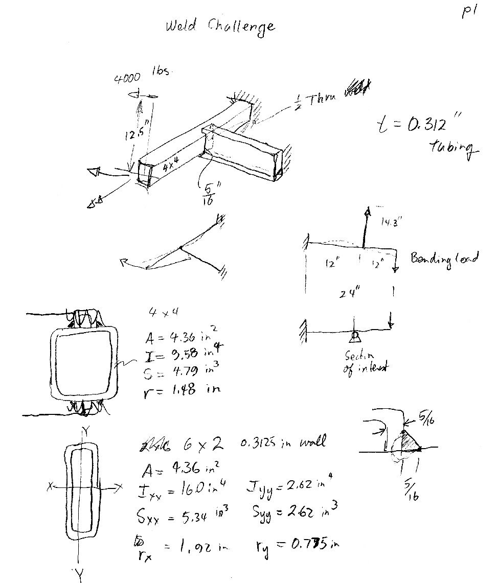
Fig. 2: Section properties assumed (Al Conle)
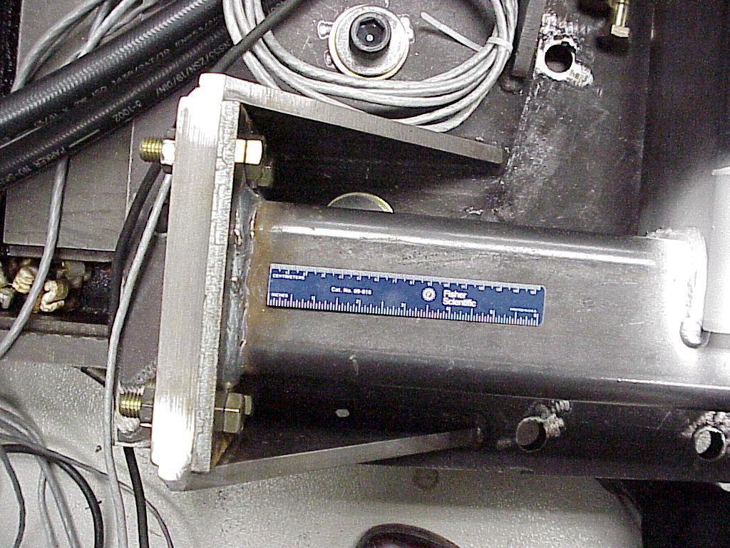
The testpiece as viewed from above is "T" shaped. The loading
arm is attached to the top left corner of the the "T". The top right
corner of the "T" is bolted into the fixture as shown below.
(The bottom leg of the "T" is anchored to the baseplate in exactly the
same fashion as the top right.)
A more oblique view of the connection:
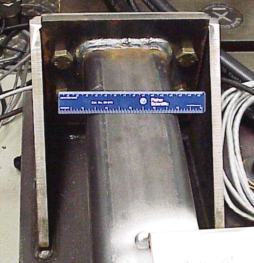
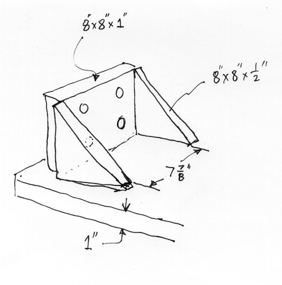
The geometry of the welded test fixture is shown below. Please note
that each plate is welded to the next and all three plates are welded
to the 1" thick baseplate.
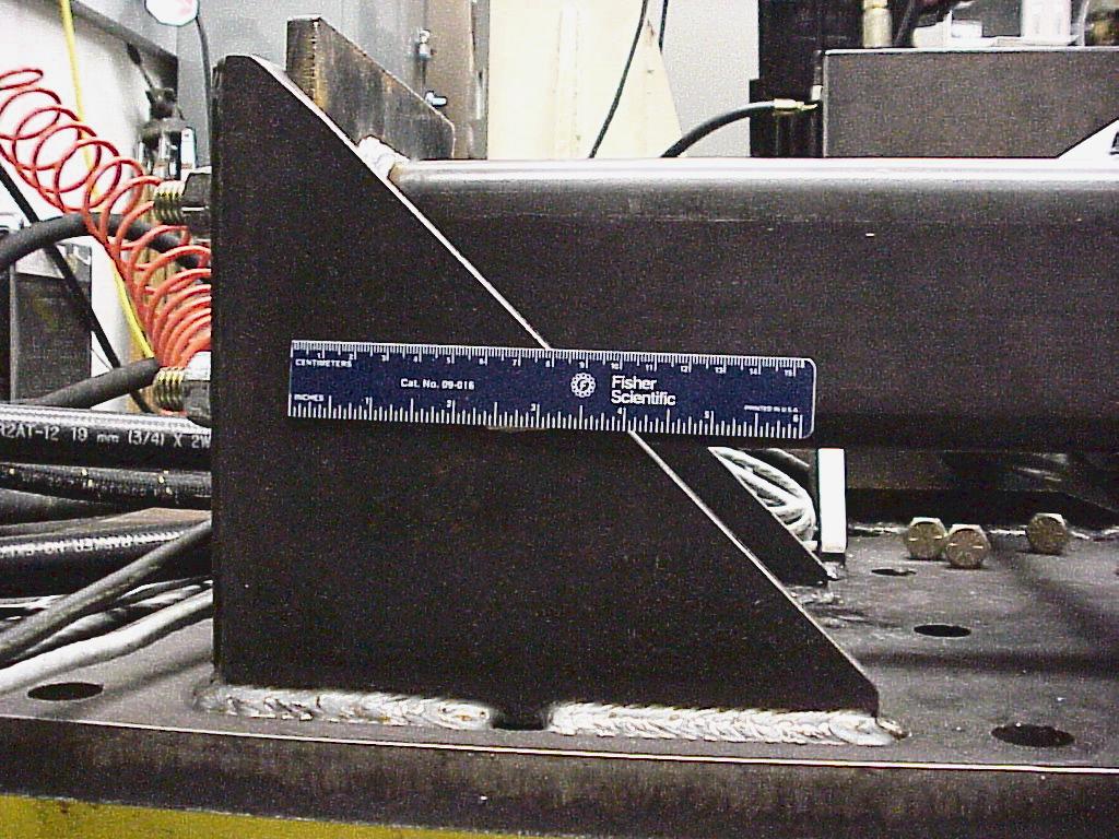
A side view showing both the base plate and specimen in
elevation. Please note that the lower bolt hole center is 4" above
the base plate:

For text file of loads see: https://fde.uwaterloo.ca/Fde/Loads/hindex.html